2012年5月22日火曜日

Tutorial 07: Texture Mapping and Constant Buffers の和訳


要約

Summary 

In the previous tutorial, we introduced lighting to our project.
Now we will build on that by adding textures to our cube. 
Also, we will introduce the concept of constant buffers, and explain how you can use buffers to speed up processing by minimizing bandwidth usage.

The purpose of this tutorial is to modify the center cube to have a texture mapped onto it.

前のチュートリアルでは、プロジェクトへのライティングについて説明しました。ここではそれを元にして、立方体にテクスチャーを追加します。また、定数バッファーの概念およびそれを使用して帯域幅使用率を最小限に抑えることで処理を高速化する方法について説明します。

このチュートリアルの目的は、中央の立方体の上にテクスチャーがマッピングされるように変更する事です。


テクスチャマッピング

Texture Mapping

Texture mapping refers to the projection of a 2D image onto 3D geometry.

テクスチャマッピングは3D幾何上の2Dイメージの投影のことを指します。

We can think of it as wrapping a present, by placing decorative paper over an otherwise bland box.

それは、平凡な箱の上に包装紙を配置する、プレゼントのラッピングと考えられます。

To do this, we have to specify how the points on the surface of the geometry correspond with the 2D image.

これをやるには、幾何表面上の頂点が2Dイメージとどの様に対応するかを指定する必要があります。

The trick is to properly align the coordinates of the model with the texture.

その方法は、モデルの座標とテクスチャーを正しく合わせるというものです。

For complex models, it is difficult to determine the coordinates for the textures by hand.

複雑なモデルでは、手動でテクスチャの座標を決めるのが難しいです。

Thus, 3D modeling packages generally will export models with corresponding texture coordinates.

そこで3Dモデリングのソフトは一般的にモデルを対応するテクスチャ座標と共にエクスポートします。

Since our example is a cube, it is easy to determine the coordinates needed to match the texture.

我々の例は立方体だからテクスチャに合わせる座標を決めるのは簡単です。

Texture coordinates are defined at the vertices, and are then interpolated for individual pixels on a surface.

テクスチャ座標は頂点として定義され、そして そこから面上に個々のピクセルが挿入されます。


テクスチャーとサンプルステートからのシェーダーリソースの作成

Creating a Shader Resource from the Texture and Sampler State


The texture is a 2D image that is retrieved from file and used to create a shader-resource view, so that it can be read from a shader.

テクスチャはファイルから回収される2D画像です。そしてそれをシェーダーから読める様にするため、シェーダーリーソースビューを作ります。

hr = D3DX11CreateShaderResourceViewFromFile
( g_pd3dDevice, L"seafloor.dds", NULL, NULL, &g_pTextureRV, NULL );

We also need to create a sampler state that controls how the shader handles filtering, MIPs, and addressing.

サンプラーステートも作る必要があります。これはシェーダーがどの様にフィルタリング、ミップマップ,そしてアドレッシングを操るかコントロールします。

For this tutorial we will enable simple sampler state that enables linear filtering and wrap addressing.

このチュートリアルでは単純なサンプラステートを有効にします。これは線形フィルタリングとラップアドレッシングを有効にします。

To create the sampler state, we will use ID3D11Device::CreateSamplerState().

サンプラステートを作るにはID3D11Device::CreateSamplerState()が使えます。

// Create the sample state
D3D11_SAMPLER_DESC sampDesc;
ZeroMemory( &sampDesc, sizeof(sampDesc) );
sampDesc.Filter = D3D11_FILTER_MIN_MAG_MIP_LINEAR;
sampDesc.AddressU = D3D11_TEXTURE_ADDRESS_WRAP;
sampDesc.AddressV = D3D11_TEXTURE_ADDRESS_WRAP;
sampDesc.AddressW = D3D11_TEXTURE_ADDRESS_WRAP;
sampDesc.ComparisonFunc = D3D11_COMPARISON_NEVER;
sampDesc.MinLOD = 0;
sampDesc.MaxLOD = D3D11_FLOAT32_MAX;
hr = g_pd3dDevice->CreateSamplerState( &sampDesc, &g_pSamplerLinear );


座標の定義

Defining the Coordinates


Before we can map the image onto our cube, we must first define the texture coordinates on each of the vertices of the cube.

立方体に画像をマッピング出来るようにするため、最初に立方体のそれぞれの頂点にテクスチャ座標を定義する必要があります。

Since images can be of any size, the coordinate system used has been normalized to [0, 1].

画像サイズが色んなサイズがあり得るので、使用される座標系を [0, 1] に正規化する必要があります。

The top left corner of the texture corresponds to (0,0) and the bottom right corner maps to (1,1).

テクスチャーの左上の隅が(0,0)に対応し、右下の隅が(1,1)にマッピングされます。

In this example, we're having the whole texture spread across each side of the cube.

この例では、テクスチャ全体を立方体のそれぞれの面に対して広げています。

This simplifies the definition of the coordinates, without confusion.

これは座標の定義を混乱なしに簡素化します。

However, it is entirely possible to specify the texture to stretch across all six faces, although it's more difficult to define the points, and it will appear stretched and distorted.

しかしながら、テクスチャーを 6 面すべてにわたって引き伸ばすように指定することは可能です。しかしこの場合、点の定義がもっと難しくなるし、伸ばされて曲げられたように見えるでしょう。

First, we updated the structure used to define our vertices to include the texture coordinates.

最初に、テクスチャ座標を含んだ頂点を定義するために構造体を作り変えました。

struct SimpleVertex
{
XMFLOAT3 Pos;
XMFLOAT2 Tex;
};

Next, we updated the input layout to the shaders to also include these coordinates.

次に、シェーダーに対するインプットレイアウトもこれらの座標を含む様に更新しました。

// インプットレイアウトの定義
D3D11_INPUT_ELEMENT_DESC layout[] =
{
{ "POSITION", 0, DXGI_FORMAT_R32G32B32_FLOAT, 0, 0, D3D11_INPUT_PER_VERTEX_DATA, 0 },
{ "TEXCOORD", 0, DXGI_FORMAT_R32G32_FLOAT, 0, 12, D3D11_INPUT_PER_VERTEX_DATA, 0 },
};

Since the input layout changed, the corresponding vertex shader input must also be modified to match the addition.

インプットレイアウトが変わったから、この追加にマッチするように対応する頂点シェーダの入力も変えなければなりません。

struct VS_INPUT
{
float4 Pos : POSITION;
float2 Tex : TEXCOORD;
};

Finally, we are ready to include texture coordinates in our vertices we defined back in Tutorial 4.

ついに、チュートリアル 4 で定義した頂点にテクスチャー座標を含める準備ができました。

Note the second parameter input is a D3DXVECTOR2 containing the texture coordinates.

入力のうちの2番目の値はテクスチャ座標を含んだD3DXVECTOR2である事に注目して下さい。
(訳注: 実際にはDirect3D11のサンプルではD3DXVECTRO2ではなくXMFLOAT2を使っています。)

Each vertex on the cube will correspond to a corner of the texture.

立方体のそれぞれの頂点はテクスチャの角と一致する事になります。

This creates a simple mapping where each vertex gets (0,0) (0,1) (1,0) or (1,1) as the coordinate.

これにより、各頂点の座標が (0,0) (0,1) (1,0) または (1,1) となる単純なマッピングが作成されます。

// Create vertex buffer
SimpleVertex vertices[] =
{
{ XMFLOAT3( -1.0f, 1.0f, -1.0f ), XMFLOAT2( 0.0f, 0.0f ) },
{ XMFLOAT3( 1.0f, 1.0f, -1.0f ), XMFLOAT2( 1.0f, 0.0f ) },
{ XMFLOAT3( 1.0f, 1.0f, 1.0f ), XMFLOAT2( 1.0f, 1.0f ) },
{ XMFLOAT3( -1.0f, 1.0f, 1.0f ), XMFLOAT2( 0.0f, 1.0f ) },

{ XMFLOAT3( -1.0f, -1.0f, -1.0f ), XMFLOAT2( 0.0f, 0.0f ) },
{ XMFLOAT3( 1.0f, -1.0f, -1.0f ), XMFLOAT2( 1.0f, 0.0f ) },
{ XMFLOAT3( 1.0f, -1.0f, 1.0f ), XMFLOAT2( 1.0f, 1.0f ) },
{ XMFLOAT3( -1.0f, -1.0f, 1.0f ), XMFLOAT2( 0.0f, 1.0f ) },

{ XMFLOAT3( -1.0f, -1.0f, 1.0f ), XMFLOAT2( 0.0f, 0.0f ) },
{ XMFLOAT3( -1.0f, -1.0f, -1.0f ), XMFLOAT2( 1.0f, 0.0f ) },
{ XMFLOAT3( -1.0f, 1.0f, -1.0f ), XMFLOAT2( 1.0f, 1.0f ) },
{ XMFLOAT3( -1.0f, 1.0f, 1.0f ), XMFLOAT2( 0.0f, 1.0f ) },

{ XMFLOAT3( 1.0f, -1.0f, 1.0f ), XMFLOAT2( 0.0f, 0.0f ) },
{ XMFLOAT3( 1.0f, -1.0f, -1.0f ), XMFLOAT2( 1.0f, 0.0f ) },
{ XMFLOAT3( 1.0f, 1.0f, -1.0f ), XMFLOAT2( 1.0f, 1.0f ) },
{ XMFLOAT3( 1.0f, 1.0f, 1.0f ), XMFLOAT2( 0.0f, 1.0f ) },

{ XMFLOAT3( -1.0f, -1.0f, -1.0f ), XMFLOAT2( 0.0f, 0.0f ) },
{ XMFLOAT3( 1.0f, -1.0f, -1.0f ), XMFLOAT2( 1.0f, 0.0f ) },
{ XMFLOAT3( 1.0f, 1.0f, -1.0f ), XMFLOAT2( 1.0f, 1.0f ) },
{ XMFLOAT3( -1.0f, 1.0f, -1.0f ), XMFLOAT2( 0.0f, 1.0f ) },

{ XMFLOAT3( -1.0f, -1.0f, 1.0f ), XMFLOAT2( 0.0f, 0.0f ) },
{ XMFLOAT3( 1.0f, -1.0f, 1.0f ), XMFLOAT2( 1.0f, 0.0f ) },
{ XMFLOAT3( 1.0f, 1.0f, 1.0f ), XMFLOAT2( 1.0f, 1.0f ) },
{ XMFLOAT3( -1.0f, 1.0f, 1.0f ), XMFLOAT2( 0.0f, 1.0f ) },
};

When we sample the texture, we will need to modulate it with a material color for the geometry underneath.

テクスチャーをサンプリングするときは、下にあるジオメトリのマテリアル カラーでそれを調整する必要があります。

 テクスチャをシェーダリソースとして登録する

Bind Texture as Shader Resource


A texture and sampler state are objects like the constant buffers that we have seen in previous tutorials.

前回のチュートリアルで定数バッファを見ましたが、テクスチャとサンプラステートはそれと似たオブジェクトです。

Before they can be used by the shader, they need to be set with the ID3D11DeviceContext::PSSetSamplers() and ID3D11DeviceContext::PSSetShaderResources() APIs.

それらがシェーダーで使われる前にID3D11DeviceContext::PSSetSamplers()ID3D11DeviceContext::PSSetShaderResources()APIsを使ってセットする必要があります。


g_pImmediateContext->PSSetShaderResources( 0, 1, &g_pTextureRV );
g_pImmediateContext->PSSetSamplers( 0, 1, &g_pSamplerLinear );

There we go, now we're ready to use the texture within the shader.

ここまでで、シェーダー内のテクスチャーを使用する準備ができました。

 テクスチャの適用

Applying the Texture


To map the texture on top of the geometry, we will be calling a texture lookup function within the pixel shader.

幾何上にテクスチャをマップするには、ピクセルシェーダー内のでテクスチャ・ルックアップ関数を呼びます。

The function Sample will perform a texture lookup of a 2D texture, and then return the sampled color.

関数Sample()は2Dテクスチャの探索(ルックアップ)を行い、そしてサンプルされた色を返します。

The pixel shader shown below calls this function and multiplies it by the underlying mesh color (or material color), and then outputs the final color.

以下で示したピクセルシェーダはこの関数を呼び、元のメッシュの色(または材質の色)を掛け、最終的な色を出力します。

●txDiffuse is the object storing our texture that we passed in from the code above, when we bound the resource view g_pTextureRV to it.

txDiffuse は、リソース ビュー g_pTextureRV をそれにバインドしたときに、上のコードから渡したテクスチャーを格納するオブジェクトです。

●samLinear will be described below; it is the sampler specifications for the texture lookup.

samLinear は、テクスチャー ルックアップのためのサンプラ仕様であり、以下で説明されています。

●input.Tex is the coordinates of the texture that we have specified in the source.

input.Tex は、ソース内で指定したテクスチャーの座標です。

// Pixel Shader(ピクセルシェーダ)
float4 PS( PS_INPUT input) : SV_Target
{
return txDiffuse.Sample( samLinear, input.Tex ) * vMeshColor;
}

Another thing we must remember to do is to pass the texture coordinates through the vertex shader.

あと忘れてはいけないのが頂点シェーダーを通じてテクスチャー座標を渡すことです。

If we don't, the data is lost when it gets to the pixel shader.

これを行わないと、それがピクセル シェーダーに到達するときにはデータは失われます。

Here, we just copy the input's coordinates to the output, and let the hardware handle the rest.

ここでは、単純に入力の座標を出力にコピーして、ハードウェアに残りを処理させます。

// Vertex Shader(頂点シェーダ)
PS_INPUT VS( VS_INPUT input )
{
PS_INPUT output = (PS_INPUT)0;
output.Pos = mul( input.Pos, World );
output.Pos = mul( output.Pos, View );
output.Pos = mul( output.Pos, Projection );
output.Tex = input.Tex;

return output;
}


定数バッファ

Constant Buffers


In Direct3D 11, an application can use a constant buffer to set shader constants (shader variables).

Direct3D 11ではアプリケーションで定数バッファーを使用してシェーダー定数 (シェーダー変数) を設定できます。

Constant buffers are declared using a syntax similar to C-style structs.

定数バッファはCスタイルの構造体に似た文法を使って宣言されます。

Constant buffers reduce the bandwidth required to update shader constants by allowing shader constants to be grouped together and committed at the same time, rather than making individual calls to commit each constant separately.

定数バッファはシェーダーの定数の更新に必要なバンド幅を減らすのに一役買います。定数バッファを使えば、それぞれのシェーダー定数を別々に渡すのではなく、更新タイミングを元にグループ化されたデータを渡す事が出来るからです。

In the previous tutorials, we used a single constant buffer to hold all of the shader constants we need.

前回のチュートリアルでは必要な全てのシェーダー定数を保持するために、一つの定数バッファを使いました。

But the best way to efficiently use constant buffers is to organize shader variables into constant buffers based on their frequency of update.

しかし定数バッファを使うベストな方法は、更新頻度に基づいて定数バッファへ入れるシェーダー変数を構成する事です。

This allows an application to minimize the bandwidth required for updating shader constants.

 これがシェーダー定数を更新する時に必要なバンド幅を最小化する事を可能にします。 


As an example, this tutorial groups constants into three structures: one for variables that change every frame, one for variables that change only when a window size is changed, and one for variables that are set once and then do not change.

例えば、このチュートリアルでは定数を3つの構造体にグループ化しました。:一つは全てのフレーム(コマ)で変わる変数用、もう一つはウインドウサイズが変わった時のみ変わる変数用、そして一旦セットされたら変わらない変数用です。

The following constant buffers are defined in this tutorial's .fx file.

以下の定数バッファはこのチュートリアルのfxファイルに定義されています。

cbuffer cbNeverChanges
{
matrix View;
};

cbuffer cbChangeOnResize
{
matrix Projection;
};

cbuffer cbChangesEveryFrame
{
matrix World;
float4 vMeshColor;
};

To work with these constant buffers, you need to create a ID3D11Buffer object for each one.

これらの定数バッファを機能させるには、それぞれに対してID3D11Bufferオブジェクトを作る必要があります。

Then you can call ID3D11DeviceContext::UpdateSubresource() to update each constant buffer when needed without affecting the other constant buffers.

そのためにID3D11DeviceContext::UpdateSubresource()を呼びます。これによって 必要な時に、他の定数バッファに影響を与える事なしに それぞれの定数バッファを更新出来ます。

//
// Update variables that change once per frame
// フレーム毎に更新する変数
CBChangesEveryFrame cb;
cb.mWorld = XMMatrixTranspose( g_World );
cb.vMeshColor = g_vMeshColor;
g_pImmediateContext->UpdateSubresource( g_pCBChangesEveryFrame, 0, NULL, &cb, 0, 0 );

Tutorial 06: Lighting の和訳

要約

Summary

In the previous tutorials, the world looks boring because all the objects are lit in the same way.

This tutorial will introduce the concept of simple lighting and how it can be applied.

The technique used will be lambertian lighting.

The outcome of this tutorial will modify the previous example to include a light source.

This light source will be attached to the cube in orbit. The effects of the light can be seen on the center cube.


以前のチュートリアルでは全てのオブジェクトが同じように照らされているため、世界は退屈に見えます。このチュートリアルでは、単純なライティングの概念およびその適用方法について説明します。この技法は、ランバートライティングとなります。

このチュートリアルでは、結果として、光源を含むように前の例を変更します。この光源は、軌道内の立方体に関連付けられます。ライトの効果は、中央の立方体で確認できます。


ライティング

Lighting

In this tutorial, the most basic type of lighting will be introduced: lambertian lighting.

このチュートリアルでは、ランバートライティングという最も基本的な種類のライトを紹介します。

Lambertian lighting has uniform intensity irrespective of the distance away from the light.

ランバートライティングでは、ライトからの距離に関係なく、強度は均一になります。

When the light hits the surface, the amount of light reflected is calculated by the angle of incidence the light has on the surface.

光が面(ポリゴン表面)にヒットした時、その入射角により光の反射率が計算されます。

When a light is shined directly on a surface, it is shown to reflect all the light back, with maximum intensity.

光が面に対して垂直に照射される時、全ての光が反射して最大の強さとなります。

However, as the angle of the light is increased, the intensity of the light will fade away.

しかしながら、光の角度が上がるに連れ、光の強さは弱まります。

To calculate the intensity that a light has on a surface, the angle between the light direction and the normal of the surface has to be calculated.

光が面上で輝く強さを計算するには、ライトの方向と面の法線の間の角度を計算する必要があります。

The normal for a surface is defined as a vector that is perpendicular to the surface.

面の法線は面に垂直なベクトルとして定義されます。

The calculation of the angle can be done with a simple dot product, which will return the projection of the light direction vector onto the normal.

角度の計算は 法線に対する光の方向のベクトルの射影を返す単純な内積で出来ます。

The wider the angle, the smaller the projection will be.

角度が広がるに連れて、射影は小さくなります。

Thus, this gives us the correct function to modulate the diffused light with.

このようにして、拡散した光を調整する適切な関数が提供されます。


The light source used in this tutorial is an approximation of directional lighting.

このチュートリアルで使われる光源は指向性照射の近似です。

The vector which describes the light source determines the direction of the light.

光源を定義するベクトルが光の方向を決定します。

Since it's an approximation, no matter where an object is, the direction in which the light shines towards it is the same.

これは近似なので、オブジェクトが何処にあってもそれを照らす光の照射方向は同じです。

An example of this light source is the sun. The sun is always seen to be shining in the same direction for all objects in a scene.

この光源の一つの例が太陽です。太陽はいつも同じ方向からシーン中の全てのオブジェクトを照らしているように見えます。

In addition, the intensity of the light on individual objects is not taken into consideration.

また、個々のオブジェクトに対するライトの強弱は考慮されません。

Other types of light include point lights, which radiate uniform light from their centers, and spot lights, which are directional but not uniform across all objects.

この他のライトの種類には、中心から均一の光を照射するポイント ライトと、指向性だが全てのオブジェクトに対して均一なわけではないスポット ライトがあります。

ライトの初期化

Initializing the Lights

In this tutorial, there will be two light sources.

このチュートリアルには2つの光源があります。

One will be statically placed above and behind the cube, and another one will be orbiting the center cube.

一つは一つの立方体の後ろ上に静的に置かれ、そしてもう一つは中央の立方体を公転します。

Note that the orbiting cube in the previous tutorial has been replaced with this light source.

前のチュートリアルで軌道を回っていた立方体が、この光源で置き換えられていることに注目してください。

Since lighting is computed by the shaders, the variables would have to be declared and then bound to the variables within the technique.

ライティングはシェーダによって計算されるので、変数を宣言してそれをテクニック内の変数と結ぶ必要があります。

In this sample, we just require the direction of the light source, as well as its color value.

このサンプルでは、光源の方向と色値だけが必要になります。

The first light is grey and not moving, while the second one is an orbiting red light.

1 つ目のライトは灰色のライトであり、移動しません。一方、2 つ目のライトは軌道を回る赤いライトです。


// ライトの設定

XMFLOAT4 vLightDirs[2] =
{
XMFLOAT4( -0.577f, 0.577f, -0.577f, 1.0f ),
XMFLOAT4( 0.0f, 0.0f, -1.0f, 1.0f ),
};
XMFLOAT4 vLightColors[2] =
{
XMFLOAT4( 0.5f, 0.5f, 0.5f, 1.0f ),
XMFLOAT4( 0.5f, 0.0f, 0.0f, 1.0f )
};

The orbiting light is rotated just like the cube in the last tutorial.

軌道を回るライトは、直前のチュートリアルの立方体と同様に回転させます。

The rotation matrix applied will change the direction of the light, to show the effect that it is always shining towards the center.

適用される回転行列により、常に中心に向って照射するようにライトの方向が変更されます。

Note that function XMVector3Transform is used to multiply a matrix with a vector.

関数XMVector3Transformは行列をベクトルに掛けるために使われる事に注目して下さい。

In the previous tutorial, we multiplied just the transformation matrices into the world matrix, then passed into the shader for transformation.

前回のチュートリアルでは、座標変換行列をワールド行列に掛けてから座標変換のためにシェーダーに渡しました。

However, for simplicity's sake in this case, we're actually doing the world transform of the light in the CPU.

しかしながら、この場合は単純化のために、実際にライトのワールド変換をCPUで行います。

// Rotate the second light around the origin
XMMATRIX mRotate = XMMatrixRotationY( -2.0f * t );
XMVECTOR vLightDir = XMLoadFloat4( &vLightDirs[1] );
vLightDir = XMVector3Transform( vLightDir, mRotate );
XMStoreFloat4( &vLightDirs[1], vLightDir );

The lights' direction and color are both passed into the shader just like the matrices.

ライトの方向と色の両方を、行列と同様にシェーダーへ渡します。

The associated variable is called to set, and the parameter is passed in.

関連する変数を設定のために呼び出し、それにパラメーターを渡します。

//
// Update matrix variables and lighting variables
// 行列変数とライティング変数の更新

ConstantBuffer cb1;
cb1.mWorld = XMMatrixTranspose( g_World );
cb1.mView = XMMatrixTranspose( g_View );
cb1.mProjection = XMMatrixTranspose( g_Projection );
cb1.vLightDir[0] = vLightDirs[0];
cb1.vLightDir[1] = vLightDirs[1];
cb1.vLightColor[0] = vLightColors[0];
cb1.vLightColor[1] = vLightColors[1];
cb1.vOutputColor = XMFLOAT4(0, 0, 0, 0);
g_pImmediateContext->UpdateSubresource( g_pConstantBuffer, 0, NULL, &cb1, 0, 0 );


ピクセルシェーダのライトの描画


Rendering the Lights in the Pixel Shader


Once we have all the data set up and the shader properly fed with data, we can compute the lambertian lighting term on each pixel from the light sources.

すべてのデータを設定し、シェーダーに正しくデータを渡したら、光源から各ピクセルのランバート ライティング項を計算できます。

We'll be using the dot product rule discussed previously.

既に説明してある内積のルールを使用します。

Once we've taken the dot product of the light versus the normal, it can then be multiplied with the color of the light to calculate the effect of that light.

一旦ライトの法線に対する内積を得たら、そのライトのエフェクトを計算するためにライトの色とそれを掛けることが出来ます。

That value is passed through the saturate function, which converts the range to [0, 1].Finally, the results from the two separate lights are summed together to create the final pixel color.

この値を、範囲を [0, 1] に変換する saturate 関数を通じて渡します。最後に、2 つの別個のライトの結果を、最終的なピクセル カラーを作成するために合計します。

Consider that the material of the surface itself is not factored into this light calculation. The final color of the surface is a result of the light's colors.

表面の材質自体はこのライトの計算の要素にはならない事を考慮して下さい。 最終的な表面の色はライトの色となります。


//
// ピクセルシェーダ
//
float4 PS( PS_INPUT input) : SV_Target
{
float4 finalColor = 0;

//do NdotL lighting for 2 lights
for(int i=0; i<2; i++)
{
finalColor += saturate( dot( (float3)vLightDir[i],input.Norm) * vLightColor[i] );
}
return finalColor;
}

Once through the pixel shader, the pixels will be modulated by the lights, and you can see the effect of each light on the cube surface.

一旦ピクセルシェーダを通過すると、ピクセルはライトによって調整され、 立方体の表面における それぞれのライトの効果が現れます。

Note that the light in this case looks flat because pixels on the same surface will have the same normal.

同じ面上のピクセルは同じ法線を持つため、この場合のライトは平面的に見えるということに注意してください。

Diffuse is a very simple and easy lighting model to compute.

ディフューズ(放散・拡散)は計算するのがとても簡単なライティングモデルです。

You can use more complex lighting models to achieve richer and more realistic materials.

あなたはもっとリッチでリアルな質感を表現するために、もっと複雑なライティングモデルを使うことも出来ます。

Tutorial 05: 3D Transformation  の和訳


概要

Summary

In the previous tutorial, we rendered a cube from model space to the screen. In this tutorial, we will extend the concept of transformations and demonstrate simple animation that can be achieved with these transformations.
The outcome of this tutorial will be an object that orbits around another. It would be useful to demonstrate the transformations and how they can be combined to achieve the desired effect. Future tutorials will be building on this foundation as we introduce new concepts.

前のチュートリアルでは立方体をモデル空間から画面空間へ描画しました。今回は座標変換の概念を拡張して単純なアニメーションを実践します。これは一連の座標変換を用いて実現する事が出来ます。

このチュートリアルの成果物は他のオブジェクトの周りを公転する物体となります。
これは座標変換と、それらの結合によって望む効果を実現するための良いデモンストレーションになるでしょう。
後のチュートリアルの新しい概念は今回の内容を基礎に置く事になるでしょう。

座標変換

Transformation

In 3D graphics, transformation is often used to operate on vertices and vectors.

3Dグラフィクスでは,  座標変換はしばしば頂点とベクトルを操作するために使われます。

It is also used to convert them in one space to another. Transformation is performed by way of multiplication with a matrix.

また、頂点やベクトルを、ある空間から別の空間へ変換するためにも使われる。座標変換は行列の乗算によって実行されます。

There are typically three types of primitive transformation that can be performed on vertices: translation (where it lies in space relative to the origin), rotation (its direction in relation to the x, y, z frame), and scaling (its distance from origin).

典型的には、頂点に対して実行できる基本的な座標変換は3タイプあります。:平行移動(頂点が原点から見て空間中の何処に位置するか)、回転(x,y,z軸に関係した頂点の方向)、スケーリング(頂点の原点からの距離)です。

In addition to those, projection transformation is used to go from view space to projection space.

これらに加え、プロジェクション変換はビュー空間からプロジェクション空間への移動に使われます。

The XNA Math library contains APIs that can conveniently construct a matrix for many purposes such as translation, rotation, scaling, world-to-view transformation, view-to-projection transformation, and so on.

XNAの算術ライブラリは様々な目的用(平行移動や、回転、スケーリング、ワールドからビュー変換、ビューから射影変換、等々)の行列を簡単に作れるAPIを含んでいます。

An application can then use these matrices to transform vertices in its scene.

なのでアプリケーションはシーン中の頂点を座標変換するのにこれらの行列を使えます。

A basic understanding of matrix transformations is required. We will briefly look at some examples below.

行列による座標変換の基礎的な理解は必要になります。以下で簡潔にいくつかの例を見ましょう。

平行移動

Translation

Translation refers to moving or displacing for a certain distance in space.

平行移動とは、空間での一定の距離の移動や配置の事を指します。

In 3D, the matrix used for translation has the form

3D では、平行移動に使用される行列は次の様な形式となります。

1   0   0   0
0   1   0   0
0   0   1   0
a   b   c   1

where (a, b, c) is the vector that defines the direction and distance to move.

(a、b、c)が表す部分はベクトルです。このベクトルが移動する方向と距離を定義します。

For example, to move a vertex -5 unit along the X axis (negative X direction), we can multiply it with this matrix:

例えばX軸の負の方向に沿って-5単位 頂点を動かすには以下の行列を掛ければ良いです。

1   0   0   0
0   1   0   0
0   0   1   0
-5  0   0   1

If we apply this to a cube object centered at origin, the result is that the box is moved 5 units towards the negative X axis, as figure 5 (訳注:( ゚д゚)図5?・・・5 unitsに引きずられた?) shows, after translation is applied.

原点を中心とする立方体の物体にこれを適用する場合は、結果として、平行移動の適用後に、図 1 の様に負の X 軸方向に 5 単位移動されます。

図1・平行移動の効果


In 3D, a space is typically defined by an origin and three unique axes from the origin: X, Y and Z.

3D では、空間は通常、原点と原点からの 3 つの固有の軸によって定義されます。:X,Y,Zです。

There are several spaces commonly used in computer graphics: object space, world space, view space, projection space, and screen space.

一般的に CGで使われる空間は複数あります。:オブジェクト空間、ワールド空間、ビュー空間、プロジェクション空間、スクリーン空間です。

オブジェクト空間に定義された立方体


回転

Rotation

Rotation refers to rotating vertices about an axis going through the origin.

回転とは、原点を通る軸に対して頂点を回転させることを指します。

Three such axes are the X, Y, and Z axes in the space.

それらの軸は3本あります。空間内のx、y、z軸です。

An example in 2D would be rotating the vector [1 0] 90 degrees counter-clockwise.

2D の例では、ベクトル [1 0] を反時計回りに 90°回転させています。

The result from the rotation is the vector [0 1].

この回転の結果は、ベクトル [0 1] となります。

The matrix used for rotating i degrees clockwise about the Y axis looks like this:

Y軸に対する時計回りの回転に使用される行列は、次の様になります。
cosθ 0 -sinθ  0
0      1    0    0
sinθ  0  cosθ  0
0      0     0   1

Figure 6(訳注:( ゚д゚){前回figure 5って書いちゃったからそれに1足しちゃった?) shows the effect of rotating a cube centered at origin for 45 degrees about the Y axis.
図 3 は、原点を中心とする立方体を Y 軸に対して 45°回転した場合の効果を示しています。

 図3. Y 軸に対する回転の効果


スケーリング

Scaling

Scaling refers to enlarging or shrinking the size of vector components along axis directions.

スケーリングとは、軸方向に沿ってベクトル成分のサイズを拡大または縮小することを指します。

For example, a vector can be scaled up along all directions or scaled down along the X axis only.

たとえば、ベクトルをすべての方向に拡大することや、X 軸方向のみに縮小することができます。

To scale, we usually apply the scaling matrix below:

スケーリングには、通常は次のようなスケーリング行列を適用します。

p   0   0   0
0   q   0   0
0   0   r   0
0   0   0   1

where p, q, and r are the scaling factor along the X, Y, and Z direction, respectively.

この場合の p q r はそれぞれ x y z 方向の拡大要素です。

The figure below shows the effect of scaling by 2 along the X axis and scaling by 0.5 along the Y axis.

図 4 は、X 方向に 2、Y 方向に 0.5 でスケーリングした場合の効果を示しています。

図4. スケーリングの効果


座標変換合成

Multiple Transformations

To apply multiple transformations to a vector, we can simply multiply the vector by the first transformation matrix, then multiply the resulting vector by the second transformation matrix, and so on.

複数の座標変換をベクトルに適用するには、単純に、そのベクトルを 1 つ目の変換行列に乗算し、次に、その結果としてもたらされたベクトルを 2つ目の変換行列に乗算し、これ以降も同様のことを行います。

Because vector and matrix multiplication is associative, we can also multiply all of the matrices first, then multiply the vector by the product matrix and obtain an identical result.

ベクトルと行列の乗算は結合可能なため、最初にすべての行列を乗算してからその積にベクトルを乗算しても、同じ結果を取得できます。

The figure below shows how the cube would end up if we combine a rotation and a translation transformation together.

図 5 は、回転と平行移動の座標変換を組み合わせた場合に立方体にもたらされる結果を示しています。

図5. 回転と平行移動の効果

軌道の作成

Creating the Orbit

In this tutorial, we will be transforming two cubes.

このチュートリアルでは2つの立方体を座標変換します。

The first one will rotate in place, while the second one will rotate around the first, while spinning on its own axis.

一つ目の立方体はその場で回転し、もう一つの立方体は一つ目の立方体を周りながら自分自身の軸でも回転します。

The two cubes will have its own world transformation matrix associated with it, and this matrix will be reapplied to it in every frame rendered.

2つの立方体は独自のワールド変換行列を持ち、その行列はすべての描画フレーム毎に適用されます。

There are functions within XNA Math that will assist in the creation of the rotation, translation, and scaling matrices.

XNA Mathには回転、移動、スケーリング行列を作るのを助ける関数があります。

  • Rotations performed around the X, Y. and Z axis are accomplished with the functions XMMatrixRotationX, XMMatrixRotationY, and XMMatrixRotationZ, respectively.They create basic rotation matrices that rotate around one of the primary axis. Complex rotations around other axis can be done by multiplying together several of them.
  • x,y,z軸周りの回転はそれぞれXMMatrixRotatinoX, ZMMatrixRotationY, XMMatrixRotationZという関数によって実行されます。これらは主軸(x,y,z)の一つを回転するという基本的な回転行列を作ります。複数の軸で回転させる複合的な回転はこれらの行列を掛け合わせる事で出来ます。
  • Translations can be performed by invoking the XMMatrixTranslation function. This function will create a matrix that will translate points specified by the parameters.
  • 平行移動はXMMatrixTranslation関数を呼び出す事によって実行できます。この関数は引数を指定して点を平行移動させる行列を作ります。
  • Scaling is done with XMMatrixScaling. It scales only along the primary axes. If scaling along arbitrary axis is desired, then the scaling matrix can be multiplied with an appropriate rotation matrix to achieve the effect.
  • スケーリングはXMMatrixScalingによって行われます。スケーリングは主軸のみに沿って行われます。恣意的な軸のスケーリングを行いたい場合、拡大行列を適切な回転行列と掛ければその効果が得られるでしょう。


The first cube will be spinning in place and act as the center for the orbit.

1 つ目の立方体は同じ位置で回転し、もう一つの公転軌道の中心の役割を果たします。

The cube has a rotation along the Y axis applied to the associated world matrix.

この立方体は関連するワールド行列によって加えられたY軸に沿った回転を持ちます。

This is done by calling the XMMatrixRotationY function shown in the following code.

これは下記のコードで示すようにXMMatrixRotationYを呼びだす事で行われます。

The cube is rotated by a set amount each frame.

立方体の回転量は各フレームの総計として現れます。

Since the cubes are suppose to continuously rotate, the value which the rotation matrix is based on gets incremented with every frame.

立方体は回転し続けることが前提となっているため、回転行列が基準とする値は、フレームごとに増大します。

// 立方体1: 原点を回る
g_World1 = XMMatrixRotationY( t );


The second cube will be orbiting around the first one.

2つ目の立方体は一つ目の周りを公転する事となります。

To demonstrate multiple transformations, a scaling factor, and its own axis spin will be added.

座標変換の合成を示すために、スケーリングの要素と、およびそれ自体の軸回転を追加しましょう。

The formula used is shown right below the code (in comments).

使われる式はコードのすぐ下にコメントで示しました。

First the cube will be scale down to 30% size, and then it will be rotated along its spin axis (the Z axis in this case).

まず立方体の大きさを30%の大きさにスケールダウンし、そしてその自転軸(この場合Z軸)に沿って回転するようにします。

To simulate the orbit, it will get translated away from the origin, and then rotated along the Y axis.

軌道をシミュレートするために、原点から離れるように平行移動させてから、そこでY軸に沿って公転させます。

The desired effect can be achieved by using four separate matrices with its individual transformation (mScale, mSpin, mTranslate, mOrbit), then multiplied together.

目的の効果は、個々の座標変換において4 つの別個の行列 (mScale、mSpin、mTranslate、mOrbit) を使用して、後で一緒に乗算することで実現できます。

// 立方体2:    Rotate around origin
XMMATRIX mSpin = XMMatrixRotationZ( -t );
XMMATRIX mOrbit = XMMatrixRotationY( -t * 2.0f );
XMMATRIX mTranslate = XMMatrixTranslation( -4.0f, 0.0f, 0.0f );
XMMATRIX mScale = XMMatrixScaling( 0.3f, 0.3f, 0.3f );
g_World2 = mScale * mSpin * mTranslate * mOrbit;

An important point to note is that these operations are not commutative.

注意すべき重要な事は、これらの操作は可換ではないという事です。

The order in which the transformations are applied matter.

座標変換の順番は重要な要素の一つです。

Experiment with the order of transformation and observe the results.

座標変換の順番を実験し、結果を観察してみてちょ。


 Since all the transformation functions will create a new matrix from the parameters, the amount at which they rotate has to be incremented.

 全ての座標変換 関数は引数から新しい行列を作成するため、引数の回転量を指す部分を増加させる必要があります。

This is done by updating the "time" variable.

これは” time ”という変数を更新することで行われます。
(訳注:実際のコードではtimeではなく、tという名前の変数が使われています。)

// 時間の更新
t += XM_PI * 0.0125f;

Before the rendering calls are made, the constant buffer must be updated for the shaders.

レンダリングの呼び出しがなされる前に、シェーダのために定数バッファを更新する必要があります。

Note that the world matrix is unique to each cube, and thus, changes for every object that gets passed into it.

ワールド行列はそれぞれの立方体で独自のものを使う事に注意して下さい。従って、オブジェクト毎に行列を付け替えます。

(訳注:エフェクトファイル(Tutorial05.fx)内のシェーダー定数は相変わらず1セット(ConstantBuffer内のWorld,View,Projection)だけを使い、C++プログラムコード側からそれを更新することで2つの立方体を書き分けています。)

//
// 最初の立方体の更新
//
ConstantBuffer cb1;
cb1.mWorld = XMMatrixTranspose( g_World1 );
cb1.mView = XMMatrixTranspose( g_View );
cb1.mProjection = XMMatrixTranspose( g_Projection );
g_pImmediateContext->UpdateSubresource( g_pConstantBuffer, 0, NULL, &cb1, 0, 0 );

//
// 最初の立方体の描画
//
g_pImmediateContext->VSSetShader( g_pVertexShader, NULL, 0 );
g_pImmediateContext->VSSetConstantBuffers( 0, 1, &g_pConstantBuffer );
g_pImmediateContext->PSSetShader( g_pPixelShader, NULL, 0 );
g_pImmediateContext->DrawIndexed( 36, 0, 0 );

//
// 立方体の更新
//
ConstantBuffer cb2;
cb2.mWorld = XMMatrixTranspose( g_World2 );
cb2.mView = XMMatrixTranspose( g_View );
cb2.mProjection = XMMatrixTranspose( g_Projection );
g_pImmediateContext->UpdateSubresource( g_pConstantBuffer, 0, NULL, &cb2, 0, 0 );

//
// 2つ目立方体の描画
//
g_pImmediateContext->DrawIndexed( 36, 0, 0 );


深度バッファ

The Depth Buffer

There is one other important addition to this tutorial, and that is the depth buffer.

このチュートリアルにはもう一つ重要な追加があります。それは深度バッファです。

Without it, the smaller orbiting cube would still be drawn on top of the larger center cube when it went around the back of the latter.

これがないと小さい公転立方体が、中央の大きい立方体の後ろに回った後も、まだ描画されてしまいます。

The depth buffer allows Direct3D to keep track of the depth of every pixel drawn to the screen.

深度バッファーは、Direct3Dが画面に描画された全てのピクセルの深さを追跡する事を可能にします。

The default behavior of the depth buffer in Direct3D 11 is to check every pixel being drawn to the screen against the value stored in the depth buffer for that screen-space pixel.

Direct3D 11の深度バッファーのデフォルトの動作では、画面に描画されている全てのピクセルが、そのスクリーン空間のピクセル用の深度バッファーに格納された値に対してチェックされます。

If the depth of the pixel being rendered is less than or equal to the value already in the depth buffer, the pixel is drawn and the value in the depth buffer is updated to the depth of the newly drawn pixel.

もし描画されたピクセルの深さが既に深度バッファの中にある値以下の場合、そのピクセルは描画されます。そして新たに描画されたピクセルが新しい深度バッファの値になります。

On the other hand, if the pixel being draw has a depth greater than the value already in the depth buffer, the pixel is discarded and the depth value in the depth buffer remains unchanged.

一方、描画しようとするピクセルが既に深度バッファの値より大きければ、そのピクセルは破棄され、深度バッファも変更されません。


 The following code in the sample creates a depth buffer (a DepthStencil texture).

 サンプル中の以下のコードは深度バッファ (深度ステンシルテクスチャ)を作ります。

It also creates a DepthStencilView of the depth buffer so that Direct3D 11 knows to use it as a Depth Stencil texture.

サンプル中では深度バッファの深度ステンシルビュ-も作ります。これにより、Direct3D11はそれを深度ステンシルテクスチャとして使うことを知ります。

// 深度ステンシル・テクスチャの作成
D3D11_TEXTURE2D_DESC descDepth;
ZeroMemory( &descDepth, sizeof(descDepth) );
descDepth.Width = width;
descDepth.Height = height;
descDepth.MipLevels = 1;
descDepth.ArraySize = 1;
descDepth.Format = DXGI_FORMAT_D24_UNORM_S8_UINT;
descDepth.SampleDesc.Count = 1;
descDepth.SampleDesc.Quality = 0;
descDepth.Usage = D3D11_USAGE_DEFAULT;
descDepth.BindFlags = D3D11_BIND_DEPTH_STENCIL;
descDepth.CPUAccessFlags = 0;
descDepth.MiscFlags = 0;
hr = g_pd3dDevice->CreateTexture2D( &descDepth, NULL, &g_pDepthStencil );
if( FAILED(hr) )
return hr;

// 深度ステンシル・ビューの作成
D3D11_DEPTH_STENCIL_VIEW_DESC descDSV;
ZeroMemory( &descDSV, sizeof(descDSV) );
descDSV.Format = descDepth.Format;
descDSV.ViewDimension = D3D11_DSV_DIMENSION_TEXTURE2D;
descDSV.Texture2D.MipSlice = 0;
hr = g_pd3dDevice->CreateDepthStencilView( g_pDepthStencil, &descDSV, &g_pDepthStencilView );
if( FAILED(hr) )
return hr;

In order to use this newly created depth stencil buffer, the tutorial must bind it to the device.

これを新しく作られた深度ステンシルバッファとして使うためには、デバイス(コンテキスト)に結び付ける必要があります。

This is done by passing the depth stencil view to the third parameter of the OMSetRenderTargets function.

これは深度ステンシルビューをOMSetRenderTargets関数の3つ目の値へ渡す事で出来ます。

g_pImmediateContext->OMSetRenderTargets( 1, &g_pRenderTargetView, g_pDepthStencilView );

As with the render target, we must also clear the depth buffer before rendering.

レンダーターゲットと一緒で、深度バッファも 描画前に クリアする必要があります。

This ensures that depth values from previous frames do not incorrectly discard pixels in the current frame.

これにより、前のフレームの深度値によって今のフレームのピクセルが誤って破棄される事が防がれます。

In the code below the tutorial is actually setting the depth buffer to be the maximum amount (1.0).

以下のチュートリアルのコードでは実際に深度値を最大値(1.0)にセッティングしています。

//
// Clear the depth buffer to 1.0 (max depth)
//
  g_pImmediateContext->ClearDepthStencilView( g_pDepthStencilView, D3D11_CLEAR_DEPTH, 1.0f, 0 );

(訳注:なぜか原著ではこのサンプルコードが抜けていました。)

Tutorial 04: 3D Spaces の和訳

概要

summary

In the previous tutorial, we successfully rendered a triangle in the center of our application window. We haven't paid much attention to the vertex positions that we have picked in our vertex buffer. In this tutorial, we will delve into the details of 3D positions and transformation. The outcome of this tutorial will be a 3D object rendered to screen. Whereas previous tutorials focused on rendering a 2D object onto a 3D world, here we show a 3D object.

前回のチュートリアルでは無事アプリケーション・ウインドウの中央に三角形を描画できました。我々は頂点バッファから取ってきた頂点の位置について余り気を払いませんでした。今回のチュートリアルでは三次元の位置と座標変換( トランスフォーム )を探求しましょう。このチュートリアルの成果は3Dのオブジェクトを画面に描画する事です。前回のチュートリアルでは3D空間に2Dオブジェクトをレンダリングする事に焦点を当てましたが、ここでは3Dオブジェクトを表示します。

3D空間

3D Spaces

In the previous tutorial, the vertices of the triangle were placed strategically to perfectly align themselves on the screen. However, this will not always be the case.

前回のチュートリアルでは、三角形の頂点は画面上に完全にそれ自身の位置で並ぶように図られて配置されました。しかし、こういったケースばかりではありません。

Thus, we need a system to denote objects in 3D space and a system to display them.

そこで物体を3D空間に示し、それを表示する座標系が必要となります。

In the real world, objects exist in 3D space.

現実の世界では、物体は3D空間に存在しています。

This means that to place an object in a particular position in the world, we would need to use a coordinate system and define three coordinates that correspond to the position.

これが意味する事は、物体を固有の位置で世界に表示するには、座標を使い、位置に対応する3つの座標を定義する必要があるという事です。

In computer graphics, 3D spaces are most commonly in Cartesian coordinate system. In this coordinate system, three axes, X, Y, and Z, perpendicular to each other, dictate the coordinate that each point in the space has.

コンピューターグラフィクスでは3D空間は一般にデカルト座標系を使って表します。この座標系はX,Y,Zの3軸が互いに直交して、空間にあるそれぞれの点を座標に取ります。

This coordinate system is further divided into left-handed and right-handed systems.

この座標系はさらに左手系と右手系に分かれています。

In a left-handed system, when X axis points to the right and Y axis points to up, Z axis points forward. In a right-handed system, with the same X and Y axes, Z axis points backward.

左手系では、X軸が右を指し、Y軸が上を指せばZ軸は奥を指します。右手系では、XとY軸が同様ならば、Z軸が手前を指します。
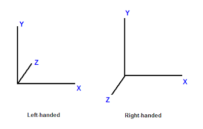
図1.座標系の違い


Now that we have talked about the coordinate system, consider 3D spaces.

これで座標系について説明出来たので、3D空間を考えましょう。

A point has different coordinates in different spaces.

一つの点は色々な空間の座標を持ちます。

As an example in 1D, suppose we have a ruler and we note the point, P, at the 5-inch mark of the ruler.

1Dの例として、定規の5インチの場所に点Pがあるとしましょう。

Now, if we move the ruler 1 inch to the right, the same point lies on the 4-inch mark.

ここでもし定規を1インチ右へ動かすと、同じ点は4インチのマークの場所にのります。

By moving the ruler, the frame of reference has changed.

定規を動かすことによって、基準となるマスが変わったのです。

Therefore, while the point hasn't moved, it has a new coordinate.

そのため、この点は動いていませんが新しい座標を持つことになります。
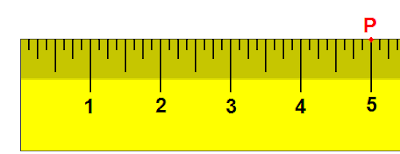
図2.1Dで表した空間

In 3D, a space is typically defined by an origin and three unique axes from the origin: X, Y and Z. There are several spaces commonly used in computer graphics: object space, world space, view space, projection space, and screen space.

3Dでは、空間は一般的に原点とそこから伸びる固有の軸(X、Y、Z)で定義されます。
CGで使われる座標空間系の種類は複数あります。:オブジェクト空間、ワールド空間、ビュー空間、プロジェクション空間、そしてスクリーン空間です。


   オブジェクト空間

Object Space

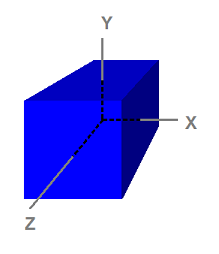
図3.オブジェクト空間に定義された立方体

Notice that the cube is centered on the origin.

この立方体は原点を中心に持つ事に注目して下さい。

Object space, also called model space, refers to the space used by artists when they create the 3D models.

オブジェクト空間はモデルスペースとも呼ばれ、デザイナーが3Dモデルを作る時に使われます。

Usually, artists create models that are centered around the origin so that it is easier to perform transformations such as rotations to the models, as we will see when we discuss transformation.

通常、デザイナーは回転などのモデルへ適用する座標変換を簡単に実行するために、原点を心にしてモデルを作ります。これは座標変換を後で説明した時に理解できるでしょう。

The 8 vertices have the following coordinates

立方体の8つの頂点は以下の座標を持ちます。

(-1, 1, -1)
( 1, 1, -1)
(-1, -1, -1)
( 1, -1, -1)
(-1, 1, 1)
( 1, 1, 1)
(-1, -1, 1)
( 1, -1, 1)

Because object space is what artists typically use when they design and create models, the models that are stored on disk are also in object space.

オブジェクト空間はデザイナーがモデルのデザインと作成をする時に使う典型的な座標系なのでディスク上に保管されているモデルのデータもオブジェクトスペースにあると言えます。

An application can create a vertex buffer to represent such a model and initialize the buffer with the model data. Therefore, the vertices in the vertex buffer will usually be in object space as well.

アプリケーションは頂点バッファをこの様なモデルを表現するために作り、そのバッファをモデルデータとして初期化出来ます。そのため、頂点バッファの頂点も通常はオブジェクト空間の座標系になります。

This also means that the vertex shader receives input vertex data in object space.

これは頂点シェーダーが入力頂点データをオブジェクト座標として受け取る事も意味します。

 ワールド空間

World Space

World space is a space shared by every object in the scene.

ワールド空間はシーンを構成する全てのオブジェクトによって共有される空間です。

It is used to define spatial relationship between objects that we wish to render.

それは描画するオブジェクト間に特別の関係を定義したい時に使われます。

To visualize world space, we could imagine that we are standing in the south-western corner of a rectangular room facing north.

ワールド空間を視覚化するには、矩形の部屋の南西の角に北に向かって立っている状態を想像して下さい。

We define the corner that our feet are standing at to be the origin, (0, 0, 0).

 我々が立っている角を原点(0, 0, 0)と定義します。

The X axis goes to our right; the Y axis goes up; and the Z axis goes forward, the same direction as we are facing.

その位置から:X軸は右へ:Y軸は上へ:Z軸は我々の向きと同じで前方へ伸びます。

When we do this, every position in the room can be identified with a set of XYZ coordinates.

このように定義すると、部屋の中の全ての位置がXYZ座標の組み合わせで表すことが出来ます。

For instance, there may be a chair 5 feet in front and 2 feet to the right of us.

例えば我々の5フィート前、2フィート右に椅子があるかも知れません。

There may be a light on the 8-foot-high ceiling directly on top of the chair.

その椅子の上、8フィートの高さには天井があり、そこにライトがあるかも知れません。

We can then refer to the position of the chair as (2, 0, 5) and the position of the light as (2, 8, 5).

その場合、椅子の位置は (2, 0, 5)で、ライトの位置は (2, 8, 5)で表せます。

As we see, world space is so-called because they tell us where objects are in relation to each other in the world.

この様に、ワールド空間は世界におけるオブジェクト同士の位置関係を教えてくれるのでその様な名前が付いています。

 ビュー空間 

View Space

View space, sometimes called camera space, is similar to world space in that it is typically used for the entire scene.

ビュース空間(カメラスペースとも呼ばれます)は通常、シーン全体のために使われるという点でワールドスペースと似ています。

However, in view space, the origin is at the viewer or camera.

ただしビュースペースでは原点がビューアー(見ている人)かカメラとなります。

The view direction (where the viewer is looking) defines the positive Z axis.

視野の方向(ビューアーが見ている方向)によってZ軸の正の向きを定義します。

An "up" direction defined by the application becomes the positive Y axis as shown below.

アプリケーションによって定義される上方向は以下に示すようにY軸の正の方向になります。
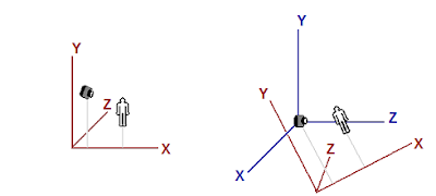
同じオブジェクトがワールドスペース(左)とビュースペース(右)にある図

The left image shows a scene that consists of a human-like object and a viewer (camera) looking at the object.

左の図は人間の様なオブジェクトとそれを見ているビューアー(カメラ)から構成されるシーンを示しています。

The origin and axes that are used by world space are shown in red.

 ワールドスペースで使われる原点と軸は赤で示しています。

The right image shows the view space in relation to world space.

右側の図はビュースペースをワールドスペースとの関連で示しています。

The view space axes are shown in blue.

ビュースペースの軸は青で示されています。

For clearer illustration, the view space does not have the same orientation as the world space in the left image to readers.

分かり易く図解するために、読み手にとって、ビュースペースの向きは左の図のワールドスペースと同じにはしていません。

Note that in view space, the viewer is looking in the Z direction.

ビュースペースではビューアーはZ軸を向いている事に注意して下さい。


(訳注:ビュー空間のまとめ
ビュー空間はビューア(カメラや人の目)を原点にして、その視線の方向をZ軸の+方向としてオブジェクトを再配置した座標空間です。ビュー座標系言った方がしっくり来るかも知れません

 プロジェクション空間

Projection Space

Projection space refers to the space after applying projection transformation from view space.

プロジェクションスペース(射影空間)とはビュースペースから プロジェクショントランスフォームを適用した後の空間の事を言います。(訳注:これに関しての詳細は下の方にある座標変換のセクションにあります。)

In this space, visible content has X and Y coordinates ranging from -1 to 1, and Z coordinate ranging from 0 to 1.

この空間では見える物は-1から1の範囲にXとYの座標を持ち、Z座標は0から1の範囲となります。

スクリーンスペース

Screen Space

Screen space is often used to refer to locations in the frame buffer.

 スクリーン空間はしばしばフレームバッファの位置を参照するのに使わます。 (訳注:フレームバッファというのはそのフレーム(描画時間単位)で最終的に出力される画面情報を収めたメモリ領域です。)

Because frame buffer is usually a 2D texture, screen space is a 2D space.

フレームバッファは通常2Dテクスチャなので、スクリーン空間は2D空間です。

The top-left corner is the origin with coordinates (0, 0). The positive X goes to right and positive Y goes down.

左上の端の座標が原点(0, 0)となります。正方向のXは右へ、正方向のYは下へ伸びます。

For a buffer that is w pixels wide and h pixels high, the most lower-right pixel has the coordinates (w - 1, h - 1).

幅wピクセルと高さhピクセルのバッファの場合、一番右下のピクセルの座標は(w -1, h -1)となります。


 空間から空間への座標変換

Space-to-space Transformation

Transformation is most commonly used to convert vertices from one space to another.

座標変換は通常、頂点をある空間から別の空間へ変換するために使われます。

In 3D computer graphics, there are logically three such transformations in the pipeline: world, view, and projection transformation.

3DCGでは理論上、パイプライン中に次のような座標変換が存在します。:ワールド、ビュー、そしてプロジェクション変換です。

Individual transformation operations such as translation, rotation, and scaling are covered in the next tutorial.

平行移動、回転、拡大縮小等の個々の変換処理は次のチュートリアルで説明します。


  ワールド変換

World Transformation

World transformation, as the name suggests, converts vertices from object space to world space.

ワールド変換は名前が示す通り、頂点をオブジェクト空間からワールド空間へ変換します。

It usually consists of one or more scaling, rotation, and translation, based on the size, orientation, and position we would like to give to the object.

 我々はオブジェクトに対してサイズや向きや位置を変更したい事があるでしょう。ワールド変換は 通常 、それらを可能にする様な、1つかそれ以上の 拡大、回転、平行移動 と言った操作の組み合わせで構成されます。

Every object in the scene has its own world transformation matrix. This is because each object has its own size, orientation, and position.

シーン中の全てのオブジェクトが独自のワールド変換行列を持ちます。なぜならそれぞれのオブジェクトが独自の大きさ、向き、そして位置を持つからです。

(訳注:厳密に言えば、個々のオブジェクトはオブジェクト空間で定義された向きと大きさをそのまま出力すれば良い場合もあるかも知れません。しかし位置がそのままだと、シーンを構成する全てのオブジェクトが同じ場所(ワールドスペースの原点)に表示されてしまうので位置のためにだけでも個々のオブジェクトに対するワールド変換が必要だったりします。)


 ビュー変換

View Transformation

After vertices are converted to world space, view transformation converts those vertices from world space to view space.

頂点がワールド空間に変換された後、ビュー変換がこれらの頂点をワールド空間からビュー空間へ変換します。

Recall from earlier discussion that view space is what the world appears from the viewer's (or camera's) perspective.

ビュー空間はビューアー(またはカメラ)から見た視野の世界として表されるという先の説明を思い出して下さい。

In view space, the viewer is located at origin looking out along the positive Z axis.

ビュー空間では、ビューアーは原点にZ軸の正の方向を向いて配置されます。

It is worth noting that although view space is the world from the viewer's frame of reference, view transformation matrix is applied to vertices, not the viewer.

ビュース空間はビューアーの座標系から見た世界であるにも関わらず、ビュー変換行列を適用するのはビューアーではなく、頂点全般だという事に注意する必要があります。

Therefore, the view matrix must perform the opposite transformation that we apply to our viewer or camera.

そういう訳でビュー行列は、ビューアーやカメラに適用するものとは逆の座標変換を実行する必要があります。

For example, if we want to move the camera 5 units towards the -Z direction, we would need to compute a view matrix that translates vertices for 5 units along the +Z direction.

例えばカメラをマイナスZ方向に5単位移動させるなら、頂点をプラスZ方向に沿って5単位平行移動させる様な ビュー行列を計算する必要があります。

Although the camera has moved backward, the vertices, from the camera's point of view, have moved forward.

そのカメラは後ろに動きますが、頂点はカメラの視点から見て前方へ動きます。

In XNA Math a convenient API call XMMatrixLookAtLH() is often used to compute a view matrix.

XNA Math の便利なAPI呼び出しのXMMatrixLookAtLH()が、しばしばビュー行列の計算に使われます。(訳注:他の行列関数一覧

We would simply need to tell it where the viewer is, where it's looking at, and the direction representing the viewer's top, also called the up-vector, to obtain a corresponding view matrix.

それを使って対応するビュー行列を得るには、単にビューアーがどこにあり、どこを見ていて、どの方向がビューアーの上(アップベクトルとも呼ばれる)なのかを教えれば良いです。


 プロジェクション変換

Projection Transformation

Projection transformation converts vertices from 3D spaces such as world and view spaces to projection space.

プロジェクショントランスフォーム(射影変換)はワールドスペースやビュースペースといった3D空間から、頂点をプロジェクションスペースへ変換します。
(訳注:Direct3D9の頃の説明も参考になります。

In projection space, X and Y coordinates of a vertex are obtained from the X/Z and Y/Z ratios of this vertex in 3D space.

プロジェクションスペースでは、頂点のXとY座標は3D空間における頂点の X/Z と Y/Zという比から得られます。
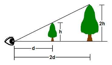
図5.プロジェクション

In 3D space, things appear in perspective. That is, the closer an object is, the larger it appears.

3D空間中の物体は遠近法で表示されます。つまり近いもの程、大きく表示されるという分けです。

As shown, the tip of a tree that is h units tall at d units away from the viewer's eye will appear at the same point as the tip of another tree 2h units tall and 2d units away.

図の様に、 ビューアーの目からd離れた所にある 高さhの木の頂上は 、2d離れた所にある高さ2hの木と同じ位置に見えます。

Therefore, where a vertex appears on a 2D screen is directly related to its X/Z and Y/Z ratios.

そういう訳で、2D画面状の何処に頂点が現れるかは、X/ZとY/Zの比と直接関連付けられます。


(訳注:ここから視野の説明がしばらく続きます。)
One of the parameters that defines a 3D space is called the field-of-view (FOV).

3D空間を定義するパラメーターの一つに視野(FOV)と呼ばれるものがあります。

FOV denotes which objects are visible from a particular position, while looking in a particular direction.

視野は特定の位置、向きの時にどのオブジェクトが見えるかを表します。

Humans have a FOV that is forward-looking (we can't see what is behind us), and we can't see objects that are too close or too far away.

人間が持つ視野は次のような特性があります。
・前向き(我々は自分の後ろにある物が見えません)
・近すぎる物や遠すぎる物は見えない。

In computer graphics, the FOV is contained in a view frustum.

コンピューターグラフィクスでは、視野は視錘台(図6)に含まれます。

(訳注:ここから視錐台の説明がしばらく続きます。)

The view frustum is defined by 6 planes in 3D.

視錐台は3次元上の6平面で定義されます。

Two of these planes are parallel to the XY plane. These are called the near-Z and far-Z planes.

これらの平面の内の2つは、XY平面に平行です。これを近-Z 平面と 遠-Z 平面と呼びます。
訳注:XY平面とは、ここでは奥行きを伴わない2D平面の事です。近、遠Z平面はクリップ平面と呼ばれたりもします。)

The other four planes are defined by the viewer's horizontal and vertical field of view.

他の4つの平面はビューアーの水平視野と垂直視野によって定義されます。

The wider the FOV is, the wider the frustum volume is, and the more objects the viewer sees.

視野が広ければ視錐台も広い事を意味し、ビューアーからはより沢山の物が見えます。

The GPU filters out objects that are outside the view frustum so that it does not have to spend time rendering something that will not be displayed. This process is called clipping.

 GPUはディスプレイに表示される事のない部分まで描画して時間を消耗す分けにはいかないので、視錐台の外のオブジェクトクトを除去します。このプロセスはクリッピングと呼ばれます。

The view frustum is a 4-sided pyramid with its top cut off.

視錐台は頂上が切り取られた四角錐です。

Clipping against this volume is complicated because to clip against one view frustum plane, the GPU must compare every vertex to the plane's equation.

この立体に対してクリッピングを行うのは複雑です。なぜなら視錐台の一つの平面に対してクリッピングを行う毎に、GPUはすべての頂点と平面の方程式で(領域内かどうかを)比較する必要があるからです。

Instead, the GPU generally performs projection transformation first, and then clips against the view frustum volume.

替りに、一般的にGPUは始めにプロジェクション変換を実行し、そして次に視錐台に対してクリッピングを行います。

(訳注:ここでクリッピングという概念を軸にして視錐台の話題がプロジェクション変換という元の話題と繋がりました。)

The effect of projection transformation on the view frustum is that the pyramid shaped view frustum becomes a box in projection space.

視錐台に対するプロジェクション変換の効果は、角錐型の視錐台がプロジェクション空間においては箱型になる事です。

This is because, as mentioned previously, in projection space the X and Y coordinates are based on the X/Z and Y/Z in 3D space.

なぜなら前に述べたように、プロジェクション空間のXとY座標は3D空間のX/ZとY/Zを元にするからです。

Therefore, point a and point b will have the same X and Y coordinates in projection space, which is why the view frustum becomes a box.

ですから、(下の図の)点aと点bはプロジェクション空間において同じXとYの座標が当てられます。これが視錐台が箱型になる理由です。
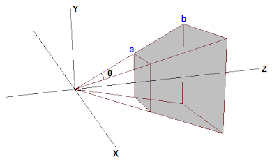
図6.視錐台


Suppose that the tips of the two trees lie exactly on the top view frustum edge.

2本の木の頂上が視錐台の上辺に正確に沿っていると仮定して下さい。

Further suppose that d = 2h.

そしてd= 2hとしましょう。
(訳注:図5参照。木までの距離をdで表し、木の高さをhで表しています。また、木の高さはその距離における視錐台の高さと一緒です。)

The Y coordinate along the top edge in projection space will then be 0.5 (because h/d = 0.5).

 その場合プロジェクションスペースでは、上辺に沿ったY座標は0.5となります(なぜなら h/d = 0.5) 。
(訳注:上の方にあった図5の解説でXとYの値がX/ZとY/Zによって決まった事を思い出して下さい。 つまり簡単に言えばプロジェクション空間までの高さ= 3D空間での高さ / Z(=距離) です。)

Therefore, any Y values post-projection that are greater than 0.5 will be clipped by the GPU.

従って投射された0.5以上のYの値はGPUによってカットされます。

The problem here is that 0.5 is determined by the vertical field of view chosen by the program, and different FOV values result in different values that the GPU has to clip against.

ここで問題なのは、この0.5という値はプログラムによって選ばれた垂直視野によって決まるものであり、視野が異なればGPUがクリップしなければならない値も違ったものになるという事です。

To make the process more convenient, 3D programs generally scale the projected X and Y values of vertices so that the visible X and Y values range from -1 to 1.

このプロセスをもっと便利にするために、3Dプログラムは一般に、表示されるXとYの範囲が-1~1となるように、射影された頂点のxとyの値を、スケーリングします。

In other words, anything with X or Y coordinate that's outside the [-1 1] range will be clipped out.

つまり、[-1 1]の範囲外の全てのxまたはy座標はカットされる事になります。

To make this clipping scheme work, the projection matrix must scale the X and Y coordinates of projected vertices by the inverse of h/d, or d/h.

このクリッピングのメカニズムを機能させるために射影行列は、 射影された頂点のXとY座標を h/dの逆、すなわちd/hによってスケーリングする必要があります。訳注:ここでのd/hのhはオブジェクトの高さではなく、オブジェクトの位置の視錐台の上辺の高さを指していると思われます。)

d/h is also the cotangent of half of FOV.

d/hは視野の半分のコタンジェントでもあります。

With scaling, the top of the view frustum becomes h/d * d/h = 1.

スケーリングによって、視錐台の頂上はh/d*d/h=1となります。

(訳注:確かにh/d*d/hという式で使われる2つのhが両方とも同じ(視錐台の上辺の高さ)なら、この式の結果は1になる分けです。しかしこれはカットの基準となる高さを表しているのであり、実際計算されるのはh/d*d/hという式の左側のhがオブジェクトの高さを、右側のhが視錐台上辺の高さを指すのだと思われます。)

Anything greater than 1 will be clipped by the GPU. This is what we want.

1より大きい物は全てGPUによってカットされます。これは我々が欲しかった挙動です。

A similar tweak is generally done for the Z coordinate in projection space as well.

同様の調整は一般にプロジェクション空間のZ座標でも行われます。

We would like the near and far Z planes to be at 0 and 1 in projection space, respectively.

我々はプロジェクション空間の近Z平面を0に、遠Z平面を1にしたいのです。

When Z = near-Z value in 3D space, Z should be 0 in projection space; when Z = far-Z in 3D space, Z should be 1 in projection space.

 Z =  3D空間上の近-Z平面 の場合はプロジェクション空間においては0になり、  Z =  3D空間上の遠-Z平面 の場合はプロジェクション空間では1になるべきです。

After this is done, any Z values outside [0 1] will be clipped out by the GPU.

それがなされた後は、[0 1]の範囲外のZ値は全て、GPUによってクリッピングされる事となります。

In Direct3D 11, the easiest way to obtain a projection matrix is to call the XMMatrixPerspectiveFovLH() method.

Direct3D11では、射影行列を得る一番簡単な方法は、XMMatrixPerspectiveFovLH()関数を呼ぶ事です。

We simply supply 4 parametersーFOVy, Aspect, Zn, and Zfーand get back a matrix that does everything necessary as mentioned above.

我々は単に4つの引数-FovAngleY, AspectHByW, NearZ,そしてFarZを供給すれば上で述べた必要な事を全てやってくれる行列が手に入ります。
(訳注:引数名がDirect3D10のチュートリアルで使われていた関数D3DXMatrixPerspectiveFovLHの引数名のままだったので修正しました)

FOVy is the field of view in Y direction. Aspect is the aspect ratio, which is ratio of view space width to height.

FOVAngleYはY方向の視野です。AspectHPyWはアスペクト比であり、ビュー空間の幅と高さの比です。

From FOVy and Aspect, FOVx can be computed.

FOVAngleXは FOVAngleY と AspectHPyW から 計算できます。

This aspect ratio is usually obtained from the ratio of the render target width to height.

このアスペクト比は通常、描画ターゲットの幅と高さの比から得ることが出来ます。

Zn and Zf are the near and far Z values in view space, respectively.

NearZとFarZ はそれぞれビュー空間における近-Z平面と遠-Z平面の値です。(訳注:つまり視野の近距離の限界と遠距離の限界です。)

 座標変換行列を使う

Using Transformation

In the previous tutorial, we wrote a program that renders a single triangle to screen.

前のチュートリアルでは画面に一つの三角形を描画するプログラムを書きました。

When we create the vertex buffer, the vertex positions that we use are directly in projection space so that we don't have to perform any transformation.

その際に頂点バッファを作った時、使用した頂点の位置はプロジェクション空間にそのまま存在したと言えるので何の座標変換も実行する必要がありませんでした。

Now that we have an understanding of 3D space and transformation, we are going to modify the program so that the vertex buffer is defined in object space, as it should be.

我々は3D空間と座標変換の知識を得たので、頂点バッファがオブジェクト空間中に適切に定義されるようにプログラムを改造しましょう。

Then, we will modify our vertex shader to transform the vertices from object space to projection space.

次に頂点をオブジェクト空間からプロジェクション空間へ変換するように頂点シェーダーを改造しましょう。


頂点バッファの改造

Modifying the Vertex Buffer

Since we started representing things in three dimensions, we have changed the flat triangle from the previous tutorial to a cube.

我々は3次元空間上の物体を表現し始めたので、描画対象を前回のチュートリアルの平面の三角形から立方体に変えました。

This will allow us to demonstrate these concepts much clearer.

これにより、一連の概念がより明確に説明できるようになるでしょう。

SimpleVertex vertices[] =
{
{ XMFLOAT3( -1.0f, 1.0f, -1.0f ), XMFLOAT4( 0.0f, 0.0f, 1.0f, 1.0f ) },
{ XMFLOAT3( 1.0f, 1.0f, -1.0f ), XMFLOAT4( 0.0f, 1.0f, 0.0f, 1.0f ) },
{ XMFLOAT3( 1.0f, 1.0f, 1.0f ), XMFLOAT4( 0.0f, 1.0f, 1.0f, 1.0f ) },
{ XMFLOAT3( -1.0f, 1.0f, 1.0f ), XMFLOAT4( 1.0f, 0.0f, 0.0f, 1.0f ) },
{ XMFLOAT3( -1.0f, -1.0f, -1.0f ), XMFLOAT4( 1.0f, 0.0f, 1.0f, 1.0f ) },
{ XMFLOAT3( 1.0f, -1.0f, -1.0f ), XMFLOAT4( 1.0f, 1.0f, 0.0f, 1.0f ) },
{ XMFLOAT3( 1.0f, -1.0f, 1.0f ), XMFLOAT4( 1.0f, 1.0f, 1.0f, 1.0f ) },
{ XMFLOAT3( -1.0f, -1.0f, 1.0f ), XMFLOAT4( 0.0f, 0.0f, 0.0f, 1.0f ) },
};


If you notice, all we did was specify the eight points on the cube, but we didn't actually describe the individual triangles.

お気付きかも知れませんが、ここでは立方体の8つの頂点を指定しただけであり、これでは個々の三角形を構成した事にはなりません。(訳注:XMFLOAT3が頂点の位置、XMFLOAT4が頂点の色です。)

If we passed this in as-is, the output would not be what we expect.

もしこれを中へそのまま通せば、出力は我々が予期したものにはならないでしょう。

We will need to specify the triangles that form the cube through these eight points.

我々は立方体を構成するこれら8つの点から三角形を指定する必要があります。

On a cube, many triangles will be sharing the same vertex and it would be a waste of space to redefine the same points over and over again.

立方体では多くの三角形が同じ頂点を共有します。同じ点を何度も再定義すると、メモリ空間の浪費になります。

As such, there is a method to specify just the eight points, and then let Direct3D know which points to pick for a triangle.

そのため、単に8つの頂点を指定し、そしてDirect3Dにそこからどの点を三角形のために選ぶかを教える…という方法があります。

This is done through an index buffer.

これはインデックスバッファを通して成されます。
(訳注:チュートリアル2でも頂点情報を節約する方法としてトライアングルストリップを扱いましたが、ここで説明されるインデックスバッファはこれとはまた別の方法です。)

An index buffer will contain a list, which will refer to the index of vertices in the buffer, to specify which points to use in each triangle.

インデックスバッファはバッファ中のどの頂点がどの三角形の中で使われるかを特定するためのリストです。

The code below shows which points make up each of our triangles.

以下のコードはどの点がどの三角形を構成するかを示します。

// インデックスバッファの作成
WORD indices[] =
{
3,1,0,
2,1,3,

0,5,4,
1,5,0,

3,4,7,
0,4,3,

1,6,5,
2,6,1,

2,7,6,
3,7,2,

6,4,5,
7,4,6,
};

As you can see, the first triangle is defined by points 3, 1, and 0.

ご覧のように、最初の三角形は点、3,1,0で定義されています。

This means that the first triangle has vertices at: ( -1.0f, 1.0f, 1.0f ),( 1.0f, 1.0f, -1.0f ), and ( -1.0f, 1.0f, -1.0f ), respectively.

これは最初の三角形が持つ頂点はそれぞれ  ( -1.0f, 1.0f, 1.0f ),( 1.0f, 1.0f, -1.0f ),  ( -1.0f, 1.0f, -1.0f ) だという事を意味します。

(訳注:インデクスバッファ WORD indices[]の中身は、 チュートリアル中の例としてその一つ上で定義した SimpleVertex vertices[]の配列の番号(インデクス)に対応してます。配列の番号は0から始まる事に注意して見比べて下さい。)

There are six faces on the cube, and each face is comprised of two triangles. Thus, you see 12 total triangles defined here.

立方体には6つの面があり、それぞれの面は2つの三角形から構成されます。そういう分けでここには合計12の三角形が定義されています。

Since each vertex is explicitly listed, and no two triangles are sharing edges (at least, in the way it has been defined), this is considered a triangle list.

それぞれの頂点は明確に並べられて、そして2つの三角形が辺を共有している訳でもありません(少なくともこの方法ではそう定義しました。)。なのでこれはトライアングルリストだと考えられます。

In total, for 12 triangles in a triangle list, we will require a total of 36 vertices.

合計では、トライアングルリストの中の12の三角形のために、合計36個の頂点が必要になります。(訳注:インデックスバッファのインデックスが36必要だという事を意味します。)

The creation of the index buffer is very similar to the vertex buffer, where we specified parameters such as size and type in a structure, and called CreateBuffer.

インデクッスバッファの作成は頂点バッファと良く似ています。構造体でサイズや型等の引数をこしらえてCreateBufferを呼びます。
(訳注:頂点バッファもインデックスバッファも型名はID3D11Bufferであり、どちらもCreateBufferを使って作成するのですね。)

The type is D3D11_BIND_INDEX_BUFFER, and since we declared our array using DWORD, we will use sizeof(DWORD).

タイプは D3D11_BIND_INDEX_BUFFERであり、DWORDを使って配列を宣言したのでsizeof(DWORD)を使います。
(訳注:タイプとはCreateBuffer()の引数にセットする構造体 D3D11_BUFFER_DESC のメンバのBindFlagsの事を指しています。このメンバはバッファの使われ方を指定します。ここではインデックスバッファとして使うのでD3D11_BIND_INDEX_BUFFERを指定します。)

D3D11_BUFFER_DESC bd;
ZeroMemory( &bd, sizeof(bd) );
bd.Usage = D3D11_USAGE_DEFAULT;
bd.ByteWidth = sizeof( WORD ) * 36; // 36 vertices needed for 12 triangles in a triangle list
bd.BindFlags = D3D11_BIND_INDEX_BUFFER;
bd.CPUAccessFlags = 0;
bd.MiscFlags = 0;
InitData.pSysMem = indices;
if( FAILED( g_pd3dDevice->CreateBuffer( &bd, &InitData, &g_pIndexBuffer ) ) )
return FALSE;


Once we created this buffer, we will need to set it so that Direct3D knows to refer to this index buffer when generating the triangles.

このバッファを作った後は、Direct3Dが三角形を製造する時にインデックスバッファを参照するのだと分かるようにセットする必要があります。

We specify the pointer to the buffer, the format, and the offset in the buffer to start referencing from.

それにはバッファへのポインター、フォーマット、そしてレンダリングを始めるバッファへがどこから開始するのかオフセットを指定します。

(訳注:オフセットというのはメモリを扱うプログラムでしばしば登場する概念です。バッファ(メモリ配列)の中には、今回描画するためのデータ意外にもデータを含める事も出来ます。オフセットは、そういったメモリ配列の中から任意のデータを指定するという意味で配列のインデックスのようなものです。何バイトデータを読み飛ばすかとう形でオフセットを指定します。今回の様にバッファ=目的のデータだけ、という場合は0を指定します。)

// インデックスバッファのセット
g_pImmediateContext->IASetIndexBuffer( g_pIndexBuffer, DXGI_FORMAT_R16_UINT, 0 );


頂点シェーダの改造

Modifying the Vertex Shader


In our vertex shader from the previous tutorial, we take the input vertex position and output the same position without any modification.

前回のチュートリアルの頂点シェーダでは頂点位置を入力として受け取り、何の変更も加えずに同じ位置を出力しました。

We can do this because the input vertex position is already defined in projection space.

これが可能なのは、入力された頂点位置が既にプロジェクション空間にあるものとして定義された場合です。

Now, because the input vertex position is defined in object space, we must transform it before outputting from the vertex shader.

今回の入力頂点はオブジェクト空間として定義したので、頂点シェーダから出力する前に座標変換をする必要があります。

We do this with three steps: transform from object to world space, transform from world to view space, and transform from view to projection space.

これは3つのステップで行います。:
オブジェクト空間からワールド空間への変換、
ワールド空間からビュー空間への変換、そして
ビュー空間からプロジェクション空間への変換です。

The first thing that we need to do is declare three constant buffer variables.

我々が初めにする必要があるのは3つの定数バッファ変数の宣言です。

Constant buffers are used to store data that the application needs to pass to shaders.

定数バッファはアプリケーションがシェーダーへ渡すのに必要なデータを格納するのに使われます。

Before rendering, the application usually writes important data to constant buffers, and then during rendering the data can be read from within the shaders.

描画の前、アプリケーションは通常、重要なデータを定数バッファに書き込みます。書き込まれた定数バッファは描画中にシェーダー内から読む事が出来ます。

In an FX file, constant buffer variables are declared like global variables in a C++ struct.

FXファイル(エフェクトファイル)では定数バッファ変数はC++のグローバル変数の構造体の様に宣言されます。

The three variables that we will use are the world, view, and projection transformation matrices of the HLSL type "matrix."

我々が使う3つの変数はHLSLの”matrix”型に属するワールド、ビュー、プロジェクション変換行列です。

Once we have declared the matrices that we will need, we update our vertex shader to transform the input position by using the matrices.

必要となる行列の宣言が済んだら頂点シェーダーを更新します。 その行列を使って入力された位置情報を変換するために、

A vector is transformed by multiplying the vector by a matrix.

ベクトルは行列を掛けることによって座標変換されます。

In HLSL, this is done using the mul() intrinsic function. Our variable declaration and new vertex shader are shown below:

HLSLでこれをするにはHLSLに元から用意されているmul()という関数を使います。
我々の変数宣言と新しい頂点シェーダーは下の通りです。

cbuffer ConstantBuffer : register( b0 )
{
matrix World;
matrix View;
matrix Projection;
}

//
// Vertex Shader
//
VS_OUTPUT VS( float4 Pos : POSITION, float4 Color : COLOR )
{
VS_OUTPUT output = (VS_OUTPUT)0;
output.Pos = mul( Pos, World );
output.Pos = mul( output.Pos, View );
output.Pos = mul( output.Pos, Projection );
output.Color = Color;
return output;
}

In the vertex shader, each mul() applies one transformation to the input position.

頂点シェーダーでは、 入力された位置に対してそれぞれのmul()が一つの座標変換を加えます。

The world, view, and projection transformations are applied in that order sequentially.

ワールド、ビュー、プロジェクション変換はその命令された順番通りにに適用されます。

This is necessary because vector and matrix multiplication is not commutative.

ベクトルと行列は可換性がないので、この事は避ける事が出来ません。
(訳注:可換性=交換法則です。a・b = b・a なら交換法則を満たします。これがないという事は、演算の順番によって結果が変わるという事を意味します。)

 行列のセットアップ

Setting up the Matrices

We have updated our vertex shader to transform using matrices, but we also need to define three matrices in our program.

頂点シェーダが行列を使って座標変換を実行するように更新をしましたが、依然としてプログラム中に3つの行列を定義する必要があります。

These three matrices will store the transformation to be used when we render.

それら3つの行列がレンダリングを行う時に使われる座標変換を格納します。

Before rendering, we copy the values of these matrices to the shader constant buffer.

レンダリングをする前、我々はこれらの行列の値をシェーダーの定数バッファにコピーします。

Then, when we initiate the rendering by calling Draw(), our vertex shader reads the matrices stored in the constant buffer.

Draw()を呼んで描画を開始する時、頂点シェーダーは定数バッファに格納された行列を読みます。

In addition to the matrices, we also need an ID3D11Buffer object that represents the constant buffer.

行列に加え、我々はID3D11Bufferオブジェクトが必要です。これが定数バッファを表します。

Therefore, our global variables will have the following addition:

そういう分けで、グローバル変数に以下の追加をしましょう。

ID3D11Buffer* g_pConstantBuffer = NULL;
XMMATRIX g_World;
XMMATRIX g_View;
XMMATRIX g_Projection;

To create the ID3D11Buffer object, we use ID3D11Device::CreateBuffer() and specify D3D11_BIND_CONSTANT_BUFFER.

ID3D11Bufferオブジェクトを作るにはID3D11Device::CreateBuffer()を使い、D3D11_BIND_CONSTANT_BUFFERを指定します。
(訳注:頂点バッファやインデックスバッファと同様、定数バッファも ID3D11Bufferと D3D11_BUFFER_DESC構造体を用意してからCreateBuffer()します。)

D3D11_BUFFER_DESC bd;
ZeroMemory( &bd, sizeof(bd) );
bd.Usage = D3D11_USAGE_DEFAULT;
bd.ByteWidth = sizeof(ConstantBuffer);
bd.BindFlags = D3D11_BIND_CONSTANT_BUFFER;
bd.CPUAccessFlags = 0;
if( FAILED(g_pd3dDevice->CreateBuffer( &bd, NULL, &g_pConstantBuffer ) ) )
return hr;

The next thing that we need to do is come up with three matrices that we will use to do the transformation.

次にする必要がある事は座標変換に使う行列を用意する事です。

We want the triangle to be sitting on origin, parallel to the XY plane.

我々は三角形をXY平面に平行に、原点を中心にしてセットしたいのです。

This is exactly how it is stored in the vertex buffer in object space.

これはオブジェクト空間の頂点バッファがどう格納されたかという事と正確に一致します。

Therefore, the world transformation needs to do nothing, and we initialize the world matrix to an identity matrix.

従って、ワールド変換は何もする必要がなく、ワールド行列は単位行列として初期化します。

We would like to set up our camera so that it is situated at [0 1 -5], looking at the point [0 1 0].

カメラは[0 1 -5]の位置に、[0 1 0]の位置を向くようにセットアップする事にしましょう。

We can call XMMatrixLookAtLH() to conveniently compute a view matrix for us using the up vector [0 1 0] since we would like the +Y direction to always stay at top.

便利なことに、XMMatrixLookAtLH()を呼べばビュー行列を計算できます。我々は+y方向が常に上になるようにしたいので上向きのベクトルを[0 1 0]にして使います。

Finally, to come up with a projection matrix, we call XMMatrixPerspectiveFovLH(), with a 90 degree vertical field of view (pi/2), an aspect ratio of 640/480 which is from our back buffer size, and near and far Z at 0.1 and 110, respectively.

最後にプロジェクション行列を用意するためにXMMatrixPerspectiveFovLH()を呼びます。90度の垂直の視界(pi/2)、640/480のアスペクト比(バックバッファのサイズ)、そして近、遠のZ平面をそれぞれと0.1と110にします。

This means that anything closer than 0.1 or further than 110 will not be visible on the screen.

これはスクリーン上の0.1より近いか110より遠い全ての物が見えなくなる事を意味します。

These three matrices are stored in the global variables g_World, g_View, and g_Projection.

これらの3つの行列はグローバル変数 g_World,g_View,g_Projectionに格納されます。


 定数バッファの更新 

Updating Constant Buffers

We have the matrices, and now we must write them to the constant buffer when rendering so that the GPU can read them.

我々は行列を手に入れましたが、今度は描画時にGPUがそれらを読めるようにするために、それらを定数バッファに書き込まなくてはなりません。

To update the buffer, we can use the ID3D11DeviceContext::UpdateSubresource() API and pass it a pointer to the matrices stored in the same order as the shader's constant buffer.

バッファの更新にはID3D11DeviceContext::UpdateSubresource() APIが使えます。そしてそれに行列が格納されたポインタを渡します。そのポインタの行列が格納されている順番は、シェーダーの定数バッファの並び方と同じです。

To help do this, we will create a structure that has the same layout as the constant buffer in the shader.

これを行うのを助けるために、我々は構造体を作ります。この構造体がシェーダ内の定数バッファと同じレイアウトを持つのです。

Also, because matrices are arranged differently in memory in C++ and HLSL, we must transpose the matrices before updating them.

C++とHLSLの行列は違ったアレンジがなされているので、更新を行う前にそれをトランスポーズ(変換)する必要があります。

//
// 変数の更新
//
ConstantBuffer cb;
cb.mWorld = XMMatrixTranspose( g_World );
cb.mView = XMMatrixTranspose( g_View );
cb.mProjection = XMMatrixTranspose( g_Projection );
g_pImmediateContext->UpdateSubresource( g_pConstantBuffer, 0, NULL, &cb, 0, 0 );


以下訳注:

構造体ConstantBufferはプログラム冒頭の構造体SimpleVertexの後に次の様に宣言されています。


struct ConstantBuffer
{
XMMATRIX mWorld;
XMMATRIX mView;
XMMATRIX mProjection;
};


また、定数バッファを使うためには、パイプラインのステージに登録するために次の関数も呼ぶ必要があります。

ID3D11DeviceContext::VSSetConstantBuffers()

この関数はTutorial04.cpp中ではRender()という関数の中で以下の様に書かれています。

//
// Renders a triangle
//
g_pImmediateContext->VSSetShader( g_pVertexShader, NULL, 0 );
 g_pImmediateContext->VSSetConstantBuffers( 0, 1, &g_pConstantBuffer );
//これ
g_pImmediateContext->PSSetShader( g_pPixelShader, NULL, 0 );
g_pImmediateContext->DrawIndexed( 36, 0, 0 ); // 36 vertices needed for 12 triangles in a triangle list


ところで・・・Render() という関数は、チュートリアル中で持続的に呼び出し続けてアニメーション描画も行える様に定義されている訳ですが・・・今回の場合、上に挙げた4つの関数の内、本当にここに必要なのは最後の描画関数だけです。

g_pImmediateContext->DrawIndexed( 36, 0, 0 );  


これ以外の○SSetなんちゃらかんちゃらみたいな関数は、一旦設定すれば持続します。だから何度も呼ばれるRender()関数内で書かなくても大丈夫です。

例えばチュートリアル中で初期化を行なっている

HRESULT InitDevice()

・・・


という関数の末尾あたりに移動してもOKです。